Apartment building with built-in premises" at the address: Leningrad region, Vsevolozhsky district, village Novosaratovka | Architectural bureau "Setl City"
A technical floor is provided under all sections of the residential building, in which technical rooms are located: a water metering unit, pumping fire extinguishing and cold water supply systems, etc. cable entries, electrical panels.
The entrances to non-residential commercial premises are separate from the entrances to the residential building.
The apartment building consists of one-, two-, three-bedroom apartments, as well as studio apartments. The quantitative composition of the apartments, their characteristics and the percentage ratio correspond to the design assignment. The distribution of apartments by floor is dictated by the conditions of the regulatory insolation of the premises. All apartments have living rooms, kitchens (kitchens-niches in studio apartments), bathrooms and bathrooms, glazed loggias. The loggias start from the 2nd floor (1st residential). In section 2 there is a studio apartment in the axes F/2-E/2 and 1/2-3/2 on the floors from the second to the fifth without a loggia.
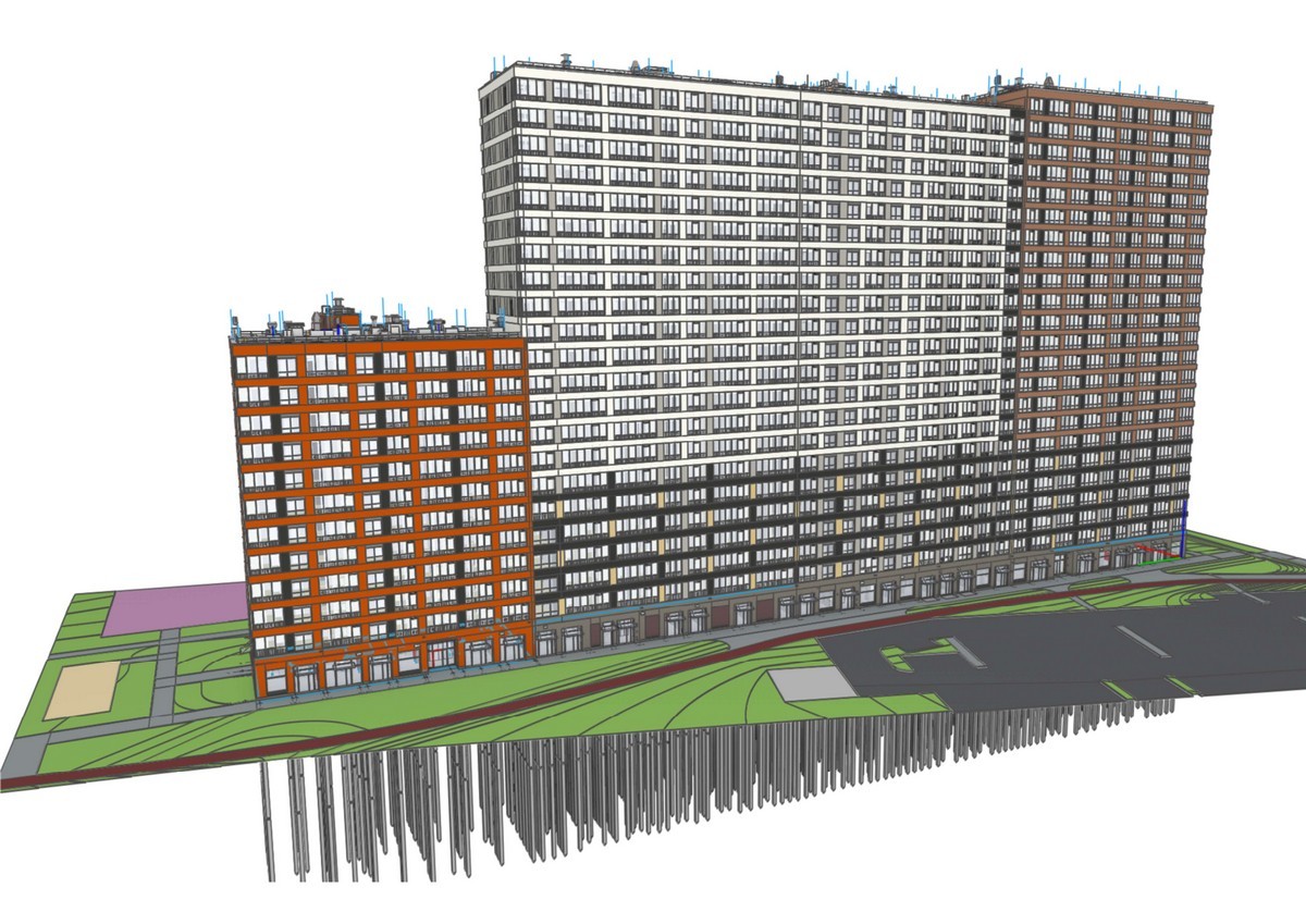
The architectural design of the facades is dictated by modern trends in the architecture of residential complexes. The facades are decorated with warm and neutral colors (light and dark shades of gray, white, bright and muted shades of orange) in contrast with the surfaces of glazed windows and stained glass windows.
The residential building is designed in monolithic reinforced concrete structures according to a mixed frame-wall structural scheme. The building's construction system is monolithic reinforced concrete. Spatial rigidity, stability, and spatial immutability of buildings are ensured by rigid embedding of piles in grillages, rigid embedding of columns, pylons, and walls in grillages, horizontal floor discs, and stiffening diaphragms. Monolithic reinforced concrete longitudinal and transverse walls serve as stiffening diaphragms. The central part of the staircase and elevator nodes forms the rigid core of the building.
The residential sections are separated by expansion joints with a size of 50 mm.
The level of the "clean" floor of the first floor is assumed to be the relative zero mark, which corresponds to the absolute mark in the Baltic height system of +13.310.
When developing Architectural solutions, composite elements were made in assemblies. Information on the modeling element was set in the assembly properties, and the internal components were filled in according to their intended purpose.
The multilayer materials were divided into finishing, insulation and the main part.
The PD and RD drawings are associatively linked to the model. Filters and customized drawing templates were used for ease of design.
Specifications, legends, markers and other elements were developed by the BIM department for designers.
The apartment marker for the Fed drawings was developed in the system and meets the necessary requirements.
The design solutions of the PD and RD stages of the facility are fully implemented in the Renga Professional software package.
Composite elements were assembled using the available functionality.
In order to obtain drawings with the correct markings, each frame, reinforcement or reinforcement part was created in the assembly and subsequently placed in the model.
Reinforcement in the project was mainly carried out with individual reinforcing rods, which needed to be given a complex shape. Such functionality as lengthening / shortening helped in the construction of the reinforcing mesh, which made it possible to change the length of all the rods at once. Individual reinforcement parts were obtained from automatic reinforcement using the "Create reinforcement rods" command.
To build the analytical model, an IFC file was used, exported from the Renga software package to the architectural design, shaping and calculation system – SAPPHIRE of the LIRA-CAD calculation complex.
After importing the IFC file into SAPPHIRE, a physical model with the previously assigned element materials was obtained.
Triangulation was performed based on the obtained analytical model, and the pull and intersection command was executed before the grid was split.
The calculation model was loaded into LIRA-CAD, where the landing on the geology was performed, the loads on the calculation scheme were set, and values were added to the tables of the DCS and RSN. Next, the calculation was performed for movement along the X, Z axis and the selection of reinforcement in the elements.